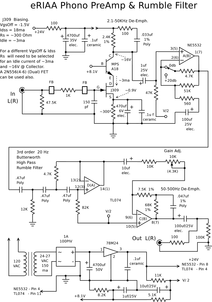
The schematic below shows the pre-amp circuit. A Signetics NE/SE5532AN op-amp is used for the preamp circuit while the high pass rumble filter uses a Texas Instruments TLO72. You could also use the Signetics amp for the rumble filter but it is the more expensive of the two. You will want to get the 5532AN version as the one with the "A" suffix has guaranteed low noise performance. The low noise version may be hard to find so use tne 5532N if it is the only one available. It still offers good noise performance along with high end clarity, much better than what is used in the todays receivers. In one brand of receiver the 4558DX is used and does not have a high enough slew rate for the use as a phono pre-amp. If your receiver uses a dual op-amp 8 pin DIP package you could just replace it with the 5532 and improve the performance that way although you will not get as low of noise as the feedback components are of a higher resistance and reactance.
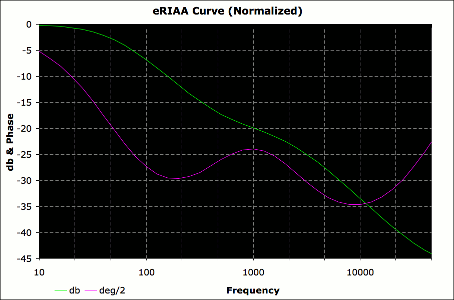
A rumble filter is included to help reduce the large signal swings of inaudible noise caused by mechanical vibration or acoustical feedback from high volume levels. This is important because it robs available headroom causing clipping during A to D conversion. Reducing signal input to compensate will reduce the signal to noise ratio of the digital signal. The pre-amp has a maximum gain of 60db at 50 Hz or lower and rolls off @ 6db/octave with a gain of 22db @ 20 KHz. With a gain of a 1000:1 @ 50 HZ or lower you can see why you need to attenuate these unwanted signals.
You can raise the low end roll off frequency by changing the µƒ capacitor to a lower value. The chart below lists the approximate roll off frequency for each capacitance value.
| Frequency @ -3db | Capacitance |
| ~14 Hz | .33µƒ |
| ~16 Hz | .3µƒ |
| ~18 Hz | .27µƒ |
| ~20 Hz | .24µƒ |
| ~22 Hz | .22µƒ |
| ~24 Hz | .2µƒ |
| ~26 Hz | .18µƒ |
| ~32 Hz | .15µƒ |
| ~40 Hz | .12µƒ |
| ~47 Hz | .1µƒ |
The .01µƒ, .0033µƒ, 24KΩ, and the 300KΩ form the feedback network that preforms the RIAA equalization. It is recomended that you definitely use polystyrene capacitors and if possible match them between the channels. Some digital voltmeters have capacitance testing so if you have one use it to select capacitors. It is also recomended that you use 1% resistors or match them also. Matching of the 300Ω resistors or using 1%ers will guarantee a good match in gain between the channels. Matching the 33µƒ capacitors will guarantee that the low end roll off frequency are close to equal although this is less critical.
Matching the 47KΩ resistors and the 150pƒ capacitors will ensure that cartridge loading between the channels will be balanced.
The µƒ capacitors in the rumble filter should be polystyrene also but if you can't find them you can use any High-Q low ESR capacitors like mylars although mylars have poor temperature coeffeceints (tending to drift in value depending on temperature). If you want you can match them also along with the 11KΩ & 62KΩ resistors.
For perfect match in signal response between left & right channels you can match all components between the both channels. The only non-critical compoments are the 100KΩ, 100Ω resistors & 100µƒ capacitor as these are for all pass DC isolation. The only reason to do this is if the program material you want to listen to has any spatial processing so exact phase and amplitude response will equal between the left & right channels. This will help preserve acoustical image of the signal.
If you can't find the larger 33µƒ & 100µƒ tantalum capacitors then use electrolytics although try to get a tantalum for the 33µƒ as they have good temperature coeffeceints and good high frequency shunting.
In the schematic "FB" designates Ferrite Beads. They are used to filter out any radio frequency interference picked up by the wiring from the cartridge to the pre-amp.
The power supply provides a regulated ±15V to the op-amps using half-wave rectification for each regulator. Using a single winding with a 18V RMS output instead of a 36V RMS center-tapped one for full-wave rectification allows easier transformer selection. Each regulator probably draws no more than 25mA of current with circuit load so a 75mA transformer is more than adequate, and you could probably get by with a 50mA one. Finding a 120VAC to 18VAC adapter that plugs into the wall would be ideal as it puts the transformer far enough away from the pre-amp and cartridge so as to not cause 60 Hz interference. If you do put the transformer into the same box as the pre-amp you need to wrap a layer of heavy copper foil around it and solder it as to create a short circuit to dampen the magnetic field that the transformer eminates.
You need to put the pre-amp in a metal box or line the inside of the box with heavy copper foil. The box also needs a ground screw for the turntable ground. For complete isolation place the power supply in one box and the pre-amp in another box but place the 1µƒ capacitors in the preamp box and not the power supply box. Connect the two boxes with 3 wires +15V,Ground,-15V.
If you do use the 5532 op-amp for the rumble filter you can allow for greater signal voltage swing by increasing the supply voltage supply to ±18V by replacing the voltage regulators with 18 volt versions 78L18 & 79L18. You will also need to increase the transformer voltage to 22V RMS but DO NOT go above 25.2V RMS as the rectified and filtered voltage will be greater than 35V and will damage the voltage regulators.

If you wish to add a headphone amp for walkman style headphones with a 16Ω impeacance the following circuit should do it. You will need to use a 100mA Transformer and replace the 220µƒ capacitors with 470µƒ ones in the power upply. The output will also drive an 8Ω load @ 70-100mW for small speakers depending on what power supply voltage is used. If you use the ±18V supply for more output power you will want to replace the regulators with 78M18 & 79M18 "M" series for added power handling capability. the "L" series is fine for the ±15V supply as long as you mount them on a heat sink. It wouldn't hurt to put a heatsink on the 5532 headphone amp also.


